Solar Gutter Light Micro Mesh Node
Platform: MeshCore / Seeed Studio XIAO nRF52840
Overview
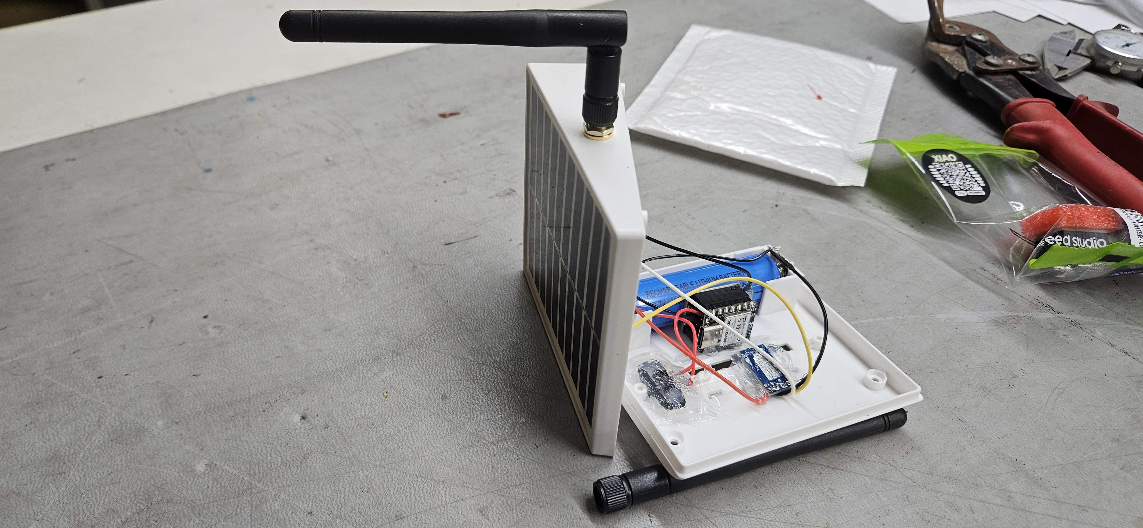
An ultra-stealth, highly affordable off-grid LoRa repeater disguised inside a commercial solar gutter accent light. By gutting the original LED circuit, retrofitting a low-profile Seeed Studio XIAO nRF52840 stack, MPPT charge controller, and mounting an external right-angle Muzi SMA whip antenna, this build seamlessly clamps to gutters, roof edges, or deck railings while providing line-of-sight network coverage.
Bill of Materials (BOM)
| Category / Item | Quantity / Packaging | Link / Supplier |
|---|---|---|
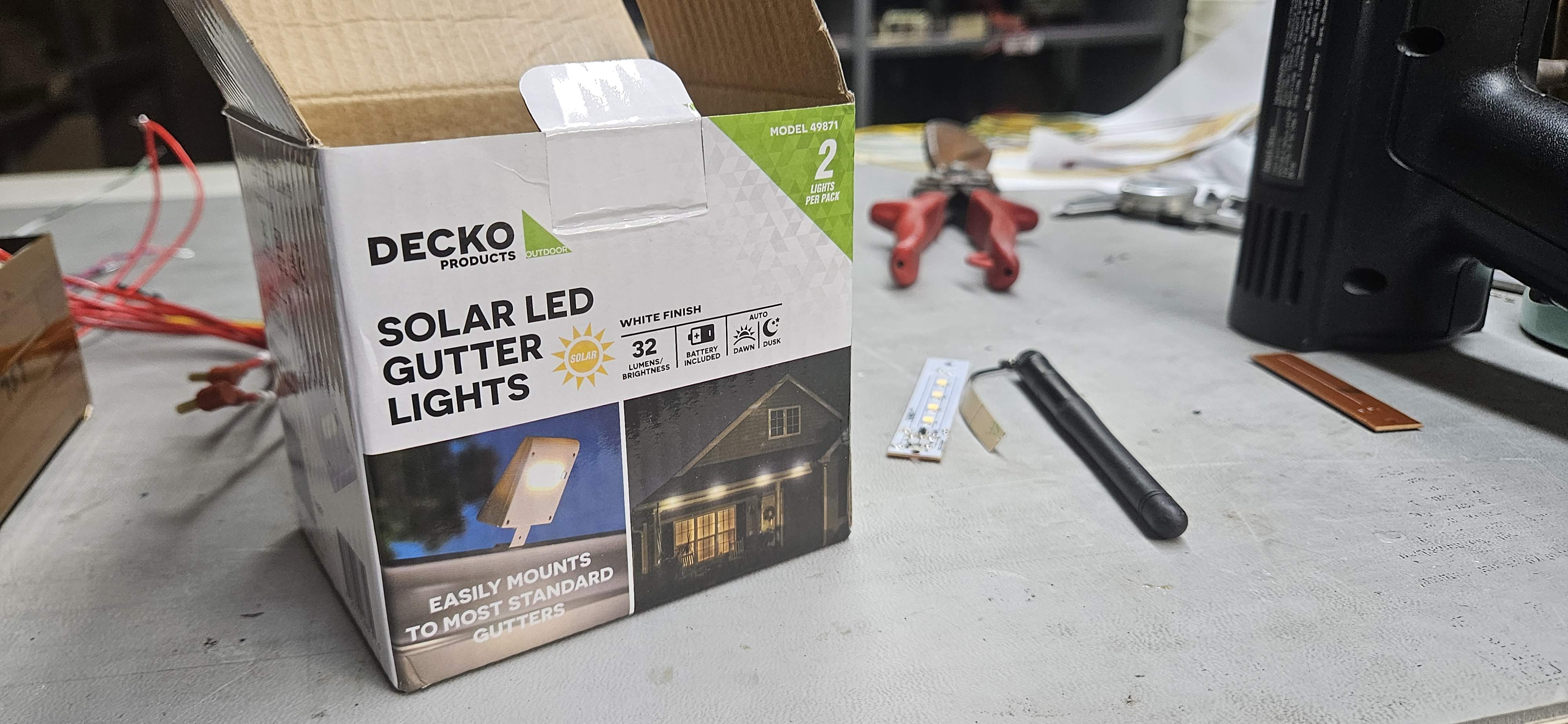
| Enclosure: Decko Solar Gutter Accent Light | 1 Unit (2-Pack) | Menards |
| Microcontroller / RF: Seeed Studio XIAO nRF52840 + SX1262 Kit | 1 Unit | Seeed Studio |
| Antenna: Muzi 915MHz SMA Whip Antenna | 1 Unit (4-Pack) | Amazon |
| RF Cabling: IPEX/U.FL to Straight SMA Female Pigtail Cable | 1 Unit | Standard Hardware |
| RF Hardware: Right-Angle SMA Male to Female Adapter | 1 Unit (4-Pack) | Amazon |
| Power / Charging: Mini Solar MPPT Charger Board | 1 Board | AliExpress |
| Protection (Optional): 1S Li-Ion BMS Protection Board | 1 Board | Amazon |
Build & Modification Steps
Step 1: Enclosure Gutting & Straight SMA Installation
Disassemble the Decko solar light shell, retaining the solar panel lid, transparent bottom window, and integrated 18650 battery holder chassis.
Carefully select a location on the upper housing for the SMA connector, double-checking internal clearances to ensure the connector and internal pigtail will not interfere with any internal supports or components when the shell is closed.
Drill a hole and install the straight SMA-to-U.FL pigtail bulkhead. Secure it with the included nut and washer. Thread the right-angle SMA adapter onto the external bulkhead port so the whip antenna can point straight up vertically when the light is mounted to a gutter.
Step 2: Board Stack Preparation & Clearances
Trim the excess length of the lower header pins on the SX1262 radio board and shorten the interfacing pin headers on the XIAO nRF52840. This allows the two boards to mate much closer together to fit inside the tight enclosure profile.
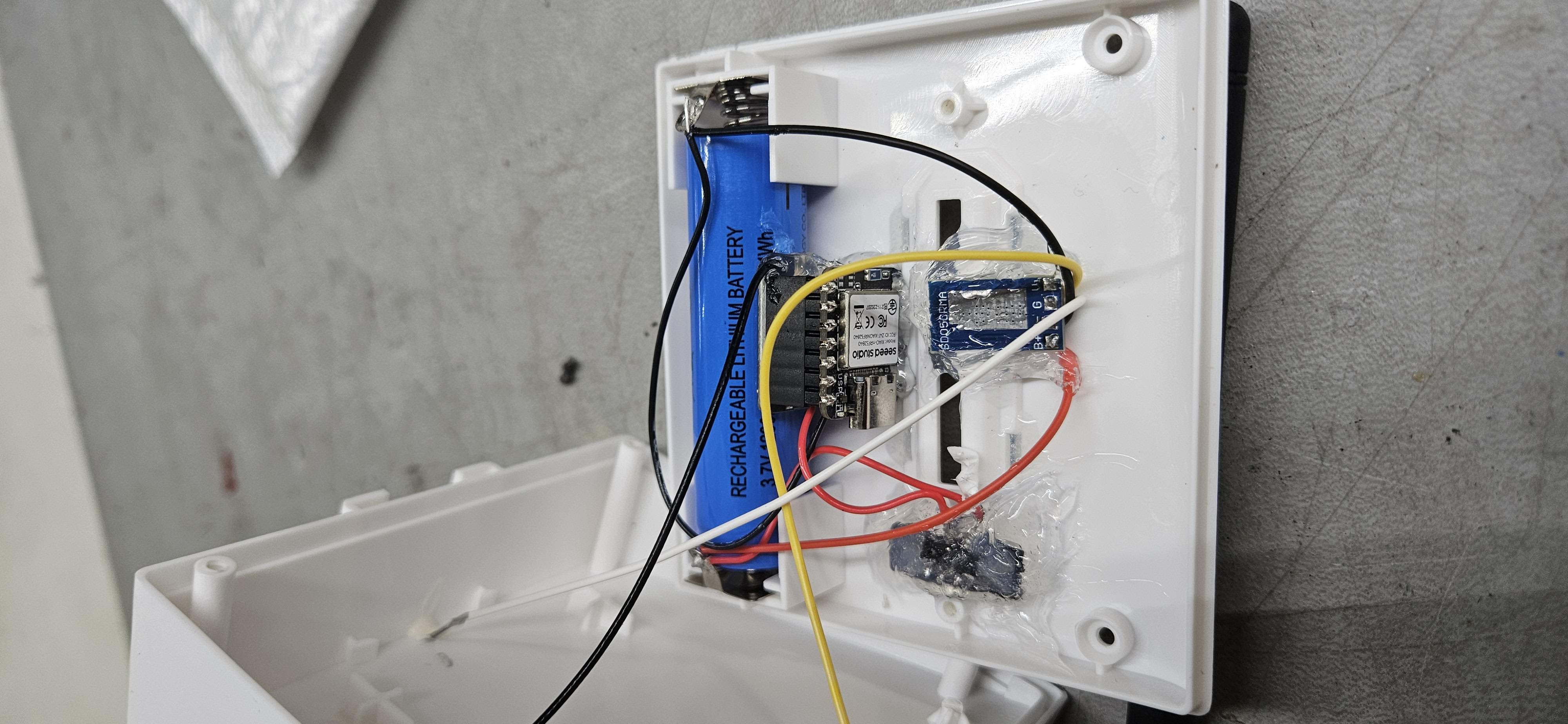
Tuck the pin-trimmed XIAO/SX1262 board stack into the narrow gap between the 18650 battery holder and the interior face of the clear lower plastic window.
Step 3: Firmware & Bootloader Flashing
Connect the XIAO nRF52840 to your computer via USB-C.
Double-tap the small reset button on the board to enter bootloader mode. The board will mount as a USB storage drive (e.g., XIAO-SENSE).
Drag and drop the OTAFIX bootloader .uf2 file directly onto the drive to update the bootloader.
Once the drive remounts, flash the preferred ZephCore/MeshCore firmware build onto the device and test board functionality before proceeding with internal wiring.
Step 4: LED Board Modification, MPPT Mounting & Wiring
Modify the original factory LED circuit board by severing specific copper traces using a utility knife. Re-wire the board to utilize its existing built-in slide switch as the primary system power switch.
Mount the mini MPPT solar charge controller directly against the modified LED board over the clear window, using the PCB to hold it firmly in place. Position it so the MPPT's charging status LEDs remain visible from the outside through the transparent lens.
Solder the solar panel leads to the Solar Input terminals on the MPPT board. Route the 18650 battery contacts through the modified slide switch to the MPPT Battery Input terminals, and run the regulated MPPT Output rails (VIN / GND) directly to the XIAO board stack.
Battery Sensing & Optional BMS: Solder a second pair of wires from the battery holder output (after the switch) directly to the two dedicated battery pads on the underside of the XIAO board to enable battery level telemetry. Note: Adding a 1S Li-Ion BMS protection board (like the one used in the solar buoy project) between the battery and the circuit is optional, but recommended for over-discharge protection.
Step 5: Antenna Connection & RF Precaution
Snap the U.FL connector of the straight SMA pigtail onto the SX1262 antenna port. Apply a small drop of hot glue or silicone over the U.FL connection to keep it secured against vibration.
Step 6: Reassembly & Outdoor Deployment
Carefully route all wiring away from pinch points and reassemble the factory light shell using the original screws. As an outdoor weather-resistant housing, additional case seam sealants are unnecessary—simply ensure the factory gasket aligns properly.
Clamp or mount the finished node onto a roof gutter, fence, or deck railing, angling the integrated solar panel south for maximum sun exposure.